Hidden Nodes
Issue
- With physical carrier sense is that all stations may not be able to hear each other.
- One client station that was about to transmit performed a CCA but did not hear another station that was already transmitting, the station that was about to transmit did not detect any RF energy during its CCA, it would transmit.
- The problem is that you then have two stations transmitting at the same time.
- The end result is a collision, and the frames will become corrupted and the frames will have to be retransmitted.

Cause
- The hidden node problem occurs when one client station’s transmissions are heard by the access point but are not heard by any or all of the other client stations in the basic service set (BSS).
- Although the access point would hear both transmissions, because two client radios are transmitting at the same time on the same frequency, the incoming client transmissions would be corrupted.
- That unheard station is the hidden node.
- What keeps occurring is that every time the hidden node transmits, another station is also transmitting and a collision occurs.
- The hidden node continues to have collisions with the transmissions from all the other stations that cannot hear it during the clear channel assessment.
- The collisions continue on a regular basis and so do the layer 2 retransmissions, with the final result being a decrease in throughput.
- A hidden node can drive retransmission rates above 15 to 20 percent or even higher. Retransmissions, of course, will affect throughput, latency, and jitter.
- Figure 12.12 shows the coverage area of an access point. Note that a thick block wall resides between one client station and all of the other client stations that are associated to the access point. The RF transmissions of the lone station on the other side of the wall cannot be heard by all of the other 802.11 client stations, even though all the stations can hear the AP.
- The hidden node problem may exist for several reasons:
- Poor WLAN design
- Obstructions such as a newly constructed wall or a newly installed bookcase.
- A user moving behind some sort of obstruction can cause a hidden node problem.
- VoWiFi phones and other mobile Wi-Fi devices often become hidden nodes because users take the mobile device into quiet corners or areas where the RF signal of the phone cannot be heard by other client stations.
- Users with wireless desktops often place their device underneath a metal desk and effectively transform the desktop radio into an unheard hidden node.
- When two client stations are at opposite ends of an RF coverage cell and they cannot hear each other, as shown in Figure 12.13.
- This often happens when coverage cells are too large as a result of the access point’s radio transmitting at too much power.
- Disable the data rates of 1 and 2 Mbps on the 2.4 GHz radio of an access point for capacity purposes.
- Another reason for disabling those data rates is that a 1 and 2 Mbps coverage cell at 2.4 GHz can be quite large and often results in hidden nodes.
- If hidden node problems occur in a network planned for coverage, then RTS/CTS may be needed.

Troubleshooting/Solution
If your end users complain of a degradation of throughput, one possible cause is a hidden node.
- A protocol analyzer is a useful tool in determining hidden node issues. If the protocol analyzer indicates a higher retransmission rate for the MAC address of one station when compared to the other client stations, chances are a hidden node has been found.
- Some protocol analyzers even have hidden node alarms based on retransmission thresholds.
- Another way is to use request to send/clear to send (RTS/CTS) to diagnose the problem. If a client device can be configured for RTS/CTS, try lowering the RTS/CTS threshold on a suspected hidden node to about 500 bytes.
- This level may need to be adjusted depending on the type of traffic being used. For instance, let’s say you have deployed a terminal emulation application in a warehouse environment and a hidden node problem exists.
- In this case, the RTS/CTS threshold should be set for a much lower size, such as 50 bytes.
- Use a protocol analyzer to determine the appropriate size.
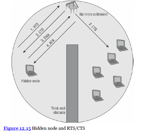
- In Figure 12.15, you see a hidden node initiating an RTS/CTS exchange.
- The stations on the other side of the obstacle may not hear the RTS frame from the hidden node, but they will hear the CTS frame sent by the access point.
- The stations that hear the CTS frame will reset their NAV for the period of time necessary for the hidden node to transmit the data frame and receive its ACK frame.
- Implementing RTS/CTS on a hidden node will reserve the medium and force all other stations to pause; thus, the collisions and retransmissions will decrease.
- Collisions and retransmissions as a result of a hidden node will cause throughput to decrease. RTS/CTS usually decreases throughput as well. However, if RTS/CTS is implemented on a suspected hidden node, throughput will probably increase due to the stoppage of the collisions and retransmissions.
- If you implement RTS/CTS on a suspected hidden node and throughput increases, you have confirmed the existence of a hidden node.
- RTS/CTS typically should not be viewed as a mechanism to fix the hidden node problem. Many legacy 802.11 client devices had the ability to adjust RTS/CTS thresholds.
In reality, most current client devices cannot be manually configured for RTS/CTS. If available, RTS/CTS can be a temporary fix for the hidden node problem but should usually be used for only diagnostic purposes. - One exception to that rule is point-to-multipoint (PtMP) bridging.
- The nonroot bridges in a PtMP scenario will not be able to hear each other because they are miles apart.
- RTS/CTS should be implemented on nonroot PtMP bridges to eliminate collisions caused by hidden node bridges that cannot hear each other.
The following methods can be used to fix a hidden node problem:
- Use RTS/CTS to diagnose: Use either a protocol analyzer or RTS/CTS to diagnose the hidden node problem. RTS/CTS can also be used as a temporary fix to the hidden node problem.
- Increase power to all stations: Most client stations have a fixed transmission power output. However, if power output is adjustable on the client side, increasing the transmission power of client stations will increase the transmission range of each station. If the transmission range of all stations is increased, the likelihood of the stations hearing each other also increases. This is not a recommended fix because increasing client power can increase cochannel interference.
- Remove the obstacles: If it is determined that some sort of obstacle is preventing client stations from hearing each other, simply removing the obstacle will solve the problem. Obviously, you cannot remove a wall, but if a metal desk or file cabinet is the obstacle, it can be moved to resolve the problem.
- Move the hidden node station: If one or two stations are in an area where they become unheard, simply moving them within transmission range of the other stations will solve the problem.
- Add another access point: If moving the hidden nodes is not an option, adding another access point in the hidden area to provide coverage will rectify the problem. The best fix for a continuous hidden node problem is to add another AP.
Near/Far
Issue
- Communication problems within a basic service set (BSS).
- A low-powered client station that is at a great distance from the access point is unheard
- Transmissions of the high-powered stations raise he noise floor near the AP to a higher level.

Cause
- Disproportionate transmit power settings between multiple clients
- The higher noise floor would corrupt the far station’s incoming frame transmissions and prevent this lower-powered station from being heard, as shown in Figure 12.11.
- Other high powered stations are very close to that access point.
- Near/far is not just caused by raising the noise floor. The problem is more often caused by an AP radio’s inability to perform automatic gain control on a very loud signal and then a very quiet signal subsequently.
- It is a bit like going to a concert and then trying to hear a whisper when you leave. It is the rapid adjustment to highly different amplitudes that causes most near/far issues. This scenario is referred to as the near/far problem.
Troubleshooting/Solution
- You can troubleshoot near/far problems with a protocol analyzer the same way you would troubleshoot the mismatched AP/client power problem.
- Please understand that the medium access methods employed by Carrier Sense Multiple Access with Collision Avoidance (CSMA/CA) usually averts the near/far problem.
- A well-planned WLAN that provides for –70 dBm or stronger coverage should also negate anyworries about near/far issues.
- The half-duplex nature of the medium usually prevents most near/far occurrences.
Weather
Issue
Outdoor Links:
- Damage to WLAN equipment
- Movement or shifting caused by wind
- Exposure to water
- Changes in air temperature can cause refraction. Bending of RF signals over long-distance point-to-point links can cause misalignment and performance issues. K-factor calculations may be necessary to compensate for refraction over long-distance links.
- UV rays and ambient heat from rooftops can damage cables over time if proper cable types are not used.
Cause
- Lightning: Direct and indirect lightning strikes can damage WLAN equipment.
- Wind: Because of the long distances and narrow beamwidths, highly directional antennas are susceptible to movement or shifting caused by wind. Even slight movement of a highly directional antenna can cause the RF beam to be aimed away from the receiving antenna, interrupting the communications.
- Water: Conditions such as rain, snow, and fog present two unique challenges.
Water damage is often a serious problem with cabling and connectors.Precipitation can also cause an RF signal to attenuate. A torrential downpour can attenuate a signal as much as 0.08 dB per mile (0.05 dB per kilometer) in both the 2.4 GHz and 5 GHz frequency ranges.
- Air Stratification: A change in air temperature at high altitudes is known as air stratification (layering). Changes in air temperature can cause refraction. Bending of RF signals over long-distance point-to-point links can cause misalignment and performance issues.
- UV/Sun: UV rays and ambient heat from rooftops can damage cables over time if proper cable types are not used.
Troubleshooting/Solution
When deploying a wireless mesh network outdoors or perhaps an outdoor bridge link, a WLAN administrator must take into account the adverse affect of weather conditions. The following weather conditions must be considered:
- Lightning: Lightning arrestors should be used for protection against transient currents. Solutions such as lightning rods or copper/fiber transceivers may offer protection against lightning strikes.
- Wind: In high wind environments, a grid antenna will typically remain more stable than a parabolic dish. Other mounting options may be necessary to stabilize the antenna from movement.
- Water: First, all outdoor equipment must be protected from damage caused by exposure to water.
Connectors should be protected with drip loops and coax seals to prevent water
damage.
Cables and connectors should be checked on a regular basis for damage.
A radome (weatherproof protective cover) should be used to protect antennas from water damage.Outdoor bridges, access points, and mesh routers should be protected from the weather elements by using appropriate National Electrical Manufacturers Association (NEMA) enclosure units.
Over long-distance bridge links, a system operating margin (SOM) of 20 dB is usually recommended to compensate for attenuation due to rain, fog, or snow. - Air Stratification: K-factor calculations may be necessary to compensate for refraction over long-distance links.
- UV/Sun: Ensure proper cable types are used.
